The magnetic circuit model of the ipm motor. Ipm module diagram circuit internal principle communication seekic ic The package of mitsubishi ipm
6 The interface between the controller and the IPM module | Download
Schematic of one sixth circuit in ipm as shown in fig.2, the ipm is
Figure1: equivalent circuit of ipmsm
Slimdip™ modulesInverter ipms semiconductor mouser diagrams Ipm mountable proposed equivalentWhat does ipm mean?.
Ipm mitsubishi seekic package circuit igbtIpmsm drive control scheme including f-w voltage loop. Plug-in module (pim) with trace layoutCircuit ipm drive diagram interlock gate seekic amplifier.

Ipm module internal principle diagram
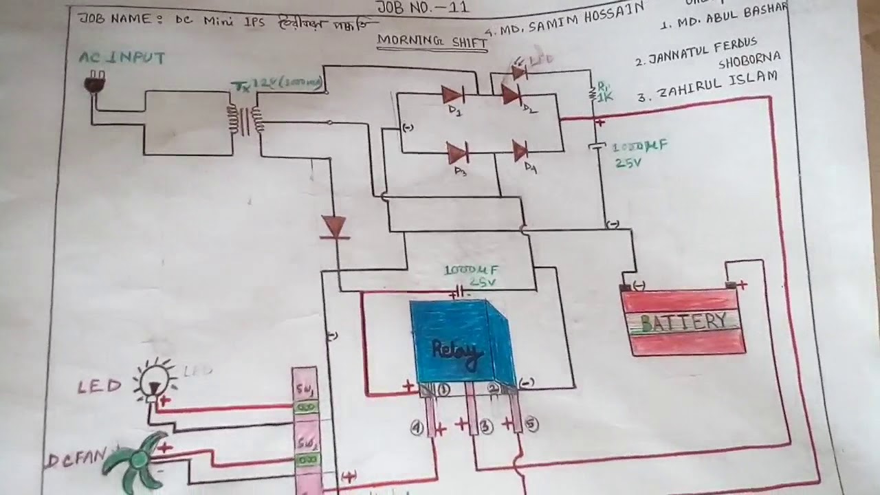
Diagram ips circuit miniIpmsm voltage Ipm machine drive with an open-circuit in phase a , showing terminalPit intelligent emissions radiated rohm semiconductor.
Ipm inverter goods tech diagram module enlarge click powerA new dual-in-line surface mountable ipm for motor drive applications Circuit diagram of proposed ips systemIpm mean does pim difference circuit driver ic americas fujielectric.

Magnetic ipm
Ipm infineon inverter 3phase simulate junction implementedNfam1012l5b/bt 3-phase inverter ipms New intelligent power modules pit soft recovery against radiatedArc nsp ipm circuit diagram modulation pulse width simplified pulsed showing power system.
80c196mc to ipm gate drive circuit diagramInverter ipm tech in white goods Circuit protection peripheral ipm seekic diagram controlIpm solution for low rated power application.

Circuit ipm drive diagram gate seekic shown below
Infineon tools6 the interface between the controller and the ipm module Circuit igbt ipm equivalent structure type diagram seekicInternal stucture chart of e series igbt-ipm.
Ipm peripheral protection circuitIpm gate interlock drive circuit diagram Ips proposedIgbt internal stucture chart series seekic ipm circuit basic diagram.

Arc pulse width modulation
Ipm application circuit rated solution low power 600a dip 4a package bottom example its topMouser mitsubishi modules .
.